

Running a 1976 Computer in Your Browser
I built a KIM-1 emulator that runs inside ASM80. Here is how, and why, and which parts fought back.
The Machine That Started Everything
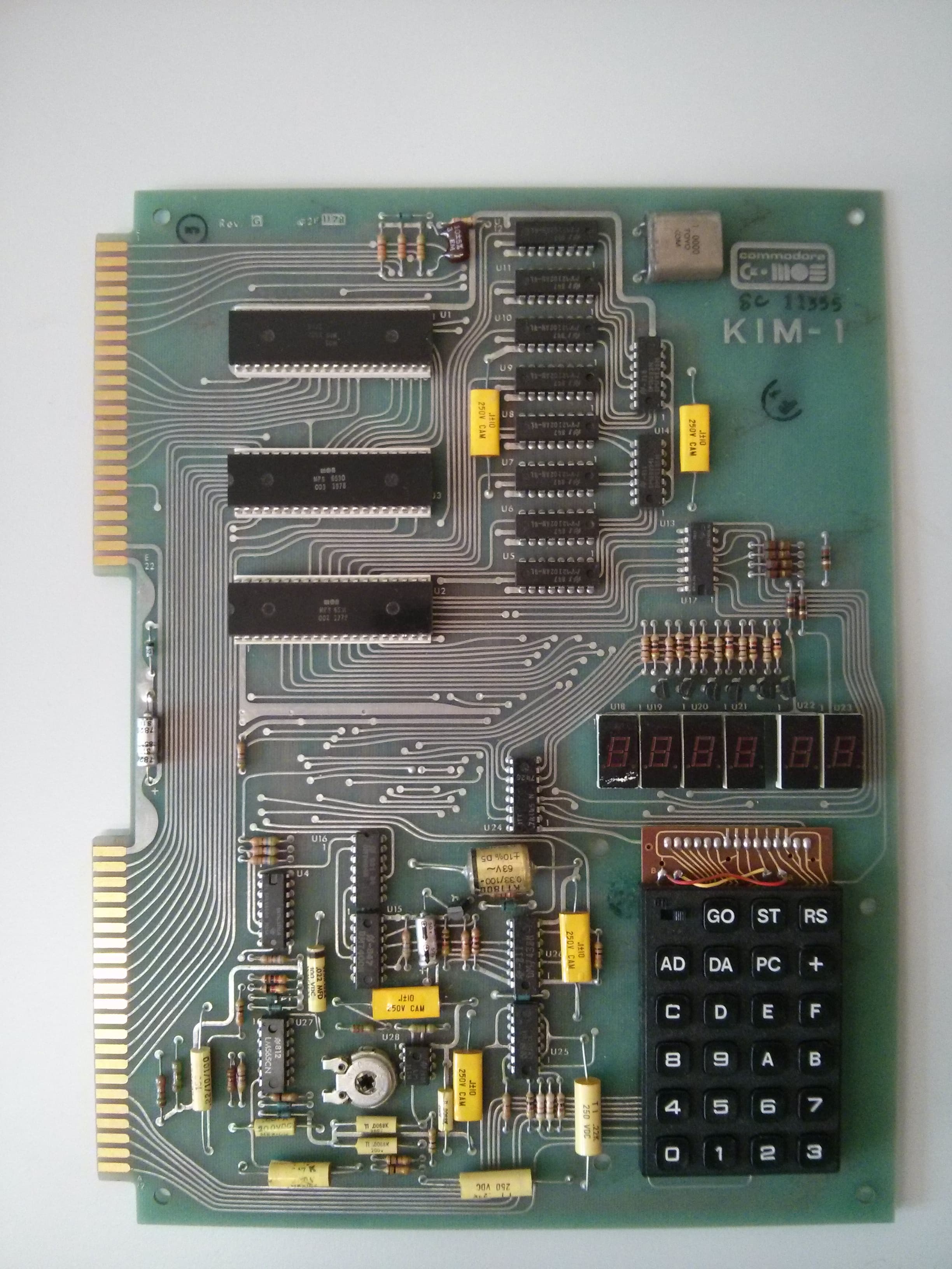
In 1975, MOS Technology had a problem. They had designed the 6502 — a CPU that could do most of what the Motorola 6800 did, at a fraction of the price — but nobody believed them. Chuck Peddle, who led the 6502 design team, understood that a datasheet alone wouldn't sell chips. Engineers needed to touch the thing, to run code on it, to prove to themselves it wasn't vaporware. So MOS built the KIM-1: a single-board computer with a hex keypad, six seven-segment LED displays, and one kilobyte of RAM. They released it in 1976 for $245.
Two hundred forty-five dollars. Adjusted for inflation, that's roughly a thousand dollars today — not cheap in an absolute sense, but in 1976 a comparable development system from Motorola or Intel would run you several thousand. The KIM-1 wasn't marketed as a personal computer. It was a development and evaluation board, a way to learn the 6502, a tool for engineers who wanted to prototype embedded systems without committing to a full product design. But something unplanned happened: hobbyists bought it. Radio clubs bought it. Students bought it. People who had no business buying a single-board computer bought one anyway, because for the first time you could afford to own a real CPU and actually program it.
What could you do with 1K of RAM? More than you'd think, and less than you'd want. The KIM-1's monitor ROM — the firmware that handled the keypad, the display, the cassette tape interface — lived in two 6530 RRIOT chips, outside of that 1K. So your full kilobyte from $0000 to $03FF was yours. People wrote games, small control programs, music generators, even a chess program (though that one needed expansion memory). The KIM-1 had an expansion connector, and a small industry grew up around selling additional RAM boards — 4K, 8K, eventually 32K and 64K. With enough expansion, you could run a real operating system. But the stock machine, with its hex keypad and its six LED digits, was where most people started.
Programs were entered by hand, one byte at a time, through the keypad. You'd look at a printed listing — often from a magazine or a user group newsletter — and punch in hex codes. If you were lucky, you had a cassette tape interface and could save your work. If you were very lucky, you had a teletype or a serial terminal and could use the KIM-1's paper tape format to load programs faster. The machine was tedious to use and completely transparent. There was no operating system, no abstraction layer, nothing between you and the hardware. That's exactly what made it a brilliant teaching tool, and exactly what makes it satisfying to emulate fifty years later.

Why Emulate This Now?
Modern computers are magnificent and opaque. You can spend years programming one without ever understanding what the CPU is actually doing. The KIM-1 is the opposite: every clock cycle is accountable, every memory access is visible, every I/O operation maps to a physical wire. When you press a key on the hex keypad, the monitor ROM scans the keyboard matrix by writing specific bit patterns to a port, then reads another port to see which key is down. When a digit appears on the LED display, it's because the ROM wrote a segment pattern to one port and a digit-select pattern to another, and it's doing this hundreds of times per second, cycling through all six digits fast enough that your eyes see a steady image.
There's no display driver, no keyboard interrupt, no HAL. Just a CPU, two I/O chips, and a clever piece of firmware. You can trace the entire path from keypress to screen update in your head, or in a debugger, without hitting any abstraction boundary you can't cross. For someone learning how computers actually work — not how to use them, but how they work — there is no better starting point than a machine this simple.
That's why I built this emulator. Not for nostalgia (I don't have any — I never owned a KIM-1), but because it's the clearest possible demonstration of what a computer does at the hardware level. And because the ASM80 IDE already has a 6502 assembler, so the toolchain was sitting right there, waiting.
The ROM Patch Trick
The KIM-1 communicates with a serial terminal through bit-banging. The 6502 runs at 1 MHz, and the serial routines in the monitor ROM toggle I/O pins in carefully timed loops to produce the right baud rate. This works on real hardware. It is a nightmare to emulate accurately.
The problem isn't the 6502 emulation — ASM80's CPU core handles that fine. The problem is timing. On a real KIM-1, the CPU executes one instruction per microsecond (give or take), and the serial routines count cycles to produce precise bit timing at 110 baud or 300 baud or whatever rate the user has configured. In an emulator, the CPU runs inside a JavaScript event loop, driven by an audio callback (more on that later), and the relationship between emulated cycles and real-world time is approximate at best. Bit-banging serial at the wrong speed produces garbage.
The classic solution is to patch the ROM. The KIM-1 monitor has two key entry points: GETCH at $1E5A (read a character from the serial port) and OUTCH at $1EA0 (write a character to the serial port). Each of these is a substantial subroutine that handles start bits, stop bits, timing loops, and error checking. In the emulator, we replace them with something much simpler.
GETCH becomes: LDA \(BFFE; RTS. Four bytes. Instead of bit-banging a serial line, the CPU just reads from a magic address. The emulator watches for reads from \)BFFE and returns whatever character the user typed into the browser-based serial terminal.
OUTCH becomes: STA $BFFF; RTS. Another four bytes. The CPU writes a character to a magic address, the emulator catches it and appends the character to the terminal output.
There's one more piece to this. The original serial routines use two zero-page variables — $EF and $F0, called CNTH30 and CNTL30 — to store the baud rate timing constants. If these aren't initialized, the monitor hangs on boot trying to auto-detect the baud rate. So the emulator pre-seeds $EF with 0x07 and $F0 with 0x27 before the first reset. The values correspond to 300 baud, but it doesn't matter what they are — the patched GETCH and OUTCH never use them. They just need to be non-zero so the auto-baud code doesn't spin forever.
The elegance of this approach is that it's invisible to user code. Any program that calls GETCH or OUTCH through the standard entry points gets the patched versions. Any program that does its own bit-banging will not work, but such programs are rare, and they wouldn't work in an emulator anyway without cycle-accurate serial timing.

The RIOT Chip and the Display/Keyboard Multiplexing
This was the hardest part of the whole project.
The KIM-1 uses two MCS 6530 RRIOT chips. "RRIOT" stands for RAM, ROM, I/O, Timer — each chip contains 64 bytes of RAM, 1K of ROM, two 8-bit I/O ports, and a programmable timer. The two RRIOTs are called RIOT-002 and RIOT-003, and between them they handle all the I/O: the keyboard, the LED display, the cassette tape interface, and the serial port (before patching).
The seven-segment displays and the keyboard share the same I/O port. This sounds insane, and it kind of is, but it made sense in 1976 when every chip cost money. Here's how it works: Port B on RIOT-002 has a Data Direction Register (DDR) that controls which bits are outputs and which are inputs. The monitor ROM constantly cycles through different DDR values. When the DDR is set to drive a particular digit of the display, the ROM writes the corresponding segment pattern to Port A, and that digit lights up. When the DDR is set to scan a particular row of the keyboard, the ROM reads Port A to see which keys are pressed.
In the emulator, we intercept writes to the Port B DDR and decode which operation the monitor is requesting. The formula is: segment = ((ddrB >> 1) & 0x0F) - 4. The result tells us what the monitor wants.
If segment is 0 through 5, we're refreshing one of the six LED digits. The value written to Port A is the segment pattern, and we update the corresponding display element.
If segment is -1, the monitor is trying to read the cassette tape input. We inject 0xFF into Port A (or the current tape bit, if a tape is loaded).
If segment is -2, -3, or -4, the monitor is scanning one of three keyboard rows. Each row covers a different set of keys. Row 0 (segment -4) handles the hex digits 0 through 6. Row 1 (segment -3) handles 7 through D. Row 2 (segment -2) handles the function keys: PC, GO, +, DA, AD, F, and E.
The keyboard encoding is active-low, which means a pressed key is represented by a 0 bit, not a 1. If the user presses key "5" on the hex keypad, and the monitor is scanning row 0, we need to inject a value where bit 5 is zero and all other bits are one. The formula is (row ^ 0x7F) | tapeBit — we XOR the row value with 0x7F to flip all the key bits to their active-low form, then OR in the tape input bit on bit 7.
Getting this right took more debugging time than everything else combined. The multiplexing happens at high speed — the monitor cycles through all display digits and keyboard rows many times per second — and any mistake in the DDR decoding, the port injection, or the active-low encoding produces symptoms that look like random garbage on the display or phantom keypresses. The kind of bug where you stare at a logic analyzer trace (well, a console.log trace) for an hour before you notice that you're shifting right by one when you should be shifting right by one and then masking.

Cassette Tape as a List of Numbers
The real KIM-1 stored programs on audio cassette tape using a variant of the Kansas City Standard. The monitor ROM toggled an output pin at specific frequencies to encode ones and zeros, and read an input pin to detect those frequencies during playback. This is frequency-shift keying (FSK), and accurately emulating it would require modeling audio waveforms, sample rates, and signal detection thresholds. None of which sounded like fun.
Instead, the emulator records cassette data as a list of T-state intervals. When the monitor toggles the tape output bit (PA7 on RIOT-002), the emulator records how many CPU cycles have elapsed since the last toggle. The result is an array of numbers: [412, 413, 207, 206, 412, ...]. Each number represents the time between two successive bit transitions, measured in clock cycles. This captures the timing information that encodes the data without dealing with audio frequencies at all.
Playback works in reverse. The emulator keeps a pointer into the interval array and a cycle counter. Each time the monitor reads the tape input bit, the emulator checks whether enough cycles have elapsed to advance to the next transition. If so, it flips the bit and moves the pointer forward. The monitor's tape-reading routine sees exactly the same timing it would see from a real cassette, because we're replaying the exact cycle counts.
This approach throws away the audio entirely and keeps only the information content. You can't listen to the tape (there's nothing to listen to), but you can save it to a file, load it back, and it works every time. No wobble, no dropout, no "please adjust the volume knob on your tape recorder." The 1970s experience, minus the 1970s frustration.
AudioContext as a Clock
An emulator needs a clock. The CPU has to execute instructions at a consistent rate, and the display has to update smoothly, and everything has to stay in sync with real time. In a browser, you have three options: setTimeout, requestAnimationFrame, or the Web Audio API. The first two are unreliable — the browser can throttle them, delay them, or skip them entirely when the tab is in the background. The Web Audio API, specifically ScriptProcessorNode, is the one thing browsers take seriously about timing, because audio glitches are audible and users complain.
The emulator creates an AudioContext at 48 kHz and a ScriptProcessorNode with a buffer size of 2048 samples. Every time the audio system needs a new buffer, it fires a callback. At 48 kHz, 2048 samples is about 42.67 milliseconds — roughly 24 frames per second. Each callback runs the CPU for the appropriate number of cycles (about 42,670 at 1 MHz), then updates the display.
The display update has a subtle trick. The KIM-1's LEDs are multiplexed — the monitor ROM lights one digit at a time, cycling through all six fast enough that they appear steady. In a 42ms frame, the monitor might refresh each digit several times, or it might not get to all of them (if the user's code is doing something time-consuming). The emulator handles this with afterglow: if a digit wasn't refreshed during the current frame, its last value is preserved on screen. If a digit was written with a null pattern (all segments off), it keeps its previous value. This mimics the phosphor-like persistence of real LED displays — not because LEDs have phosphor, but because the human eye retains the image of a briefly-lit digit for a few tens of milliseconds. The effect is the same. Without afterglow, the display flickers horribly. With it, the digits appear steady, exactly as they do on a real KIM-1.
Yes, ScriptProcessorNode is deprecated. Yes, I should migrate to AudioWorklet. It's on the list. The deprecated API works in every browser today, and when it stops working, I'll deal with it. Premature migration is the root of all... well, not evil, but definitely wasted weekends.
SST Mode
The KIM-1 has a hardware single-step mode, controlled by a physical toggle switch on the board. When SST is on, the CPU executes one instruction, then immediately takes a Non-Maskable Interrupt (NMI). The NMI vector points into the monitor ROM, which displays the current registers and waits for the user to press GO to execute the next instruction.
On the real hardware, this works because the SST switch is wired to the NMI line through some edge-detection logic. After each instruction completes, if the switch is in the SST position, the hardware triggers an NMI.
In the emulator, the entire mechanism is one line of JavaScript. After each instruction executes, if the SST flag is set, call cpu.nmi(). That's it. The monitor ROM handles everything else — saving registers, displaying them on the LEDs, waiting for GO — exactly as it does on the real machine. The ROM doesn't know or care that the NMI came from a JavaScript boolean instead of a physical switch. An NMI is an NMI.
The toggle switch itself is rendered as an HTML checkbox, injected into the SVG front panel image via a <foreignObject> element. It sits right where the real switch would be. Click it on, and every instruction triggers NMI. Click it off, and the CPU runs free. The checkbox maps to a boolean, the boolean maps to an NMI call, and the original 1976 hardware design just... works, unchanged, fifty years later, in a browser.
This was the easiest part of the whole project. I kept waiting for it to be more complicated. It wasn't.
MOS Papertape Format
Before there were hex files (Intel HEX, Motorola S-records), MOS Technology defined their own format for storing programs on paper tape. The KIM-1 uses it for loading and saving programs through the serial port, and ASM80 supports it for uploading code to the emulator.
Each record starts with a semicolon and has the format: ;LLAAAADDDD...DDSS. LL is the byte count (how many data bytes follow). AAAA is the starting address, big-endian. Then come the data bytes, each as two hex digits. Finally, SS is a 16-bit checksum, stored big-endian with the high byte first.
The checksum is the sum of the byte count, the address high byte, the address low byte, and all the data bytes, modulo 65536. It's stored in two bytes, high byte first — which is the opposite of the 6502's native little-endian byte order. I assume this made sense to someone at MOS Technology in 1976. Maybe they were Motorola alumni. Maybe they just liked big-endian checksums. I didn't ask.
The end-of-file record is always ;0000040001. Zero data bytes, address $0004, checksum $0001. Why address $0004? It's the reset vector for the monitor — pressing GO jumps through $0004. The checksum is \(0001 because 0x00 + 0x00 + 0x04 = 0x0004... wait, that's \)0004, not $0001. The end record is actually a special case; the checksum value $0001 is a convention, not a computed value. The loader recognizes it as the terminator.
In the ASM80 IDE, you can load .pap files directly into the emulator's memory. The parser reads each record, validates the checksum, and writes the data bytes to the specified addresses. Saving works in reverse: select an address range, and the IDE generates .pap records with correct checksums. It's a simple format — no compression, no relocation, no metadata — and that simplicity is exactly why it's still easy to work with half a century later.
Why It's Satisfying
The KIM-1 is a machine simple enough to hold in your head. All of it. The CPU has 56 instructions, 13 addressing modes, and three registers that matter (A, X, Y plus the status flags). The address space is 64K, of which only 2K is ROM and 1K is RAM. The I/O is two chips with two ports each. The monitor firmware is about 2K of hand-written 6502 assembly. You can understand the whole thing — not superficially, not "I get the general idea," but actually understand every byte, every pin, every timing constraint.
That's why it was a teaching tool in 1976, and that's why it's still a teaching tool now. When you type a hex value on the keypad and watch it appear on the LED display, you can trace the entire path: the keyboard scan in the monitor ROM, the DDR writes to the RIOT, the port reads, the lookup table for the key code, the segment pattern write, the display multiplex cycle. There's nothing hidden. There's nothing you have to take on faith.
Modern computers are better at everything except being understandable. The KIM-1 is worse at everything except being transparent. And transparency, it turns out, is the one thing you can't get from a faster chip.
The emulator runs at asm80.com. Load a .pap file, flip the SST switch, step through the monitor ROM one instruction at a time, and watch a fifty-year-old design do its work. It's the same machine Chuck Peddle's team built to prove that their cheap little CPU was real. It's still proving it.